What is PoE (Power over Ethernet)?
PoE (Power over Ethernet) is the name of a number of methods that allow for powering network devices through UTP/FTP cables. This allows devices like Security Cameras, Phones, Network Switches, or Antennas to send and receive data and power with just one cable.
The two standard types of PoE are 802.3af and 802.3at.
Comparison of PoE and PoE+ Types:
|
Feature/standard |
802.3af (802.3at type 1 ) |
802.3at type 2 (POE+) |
| Output power of power supply [W] | 15.40 | 30.00* |
|
Minimum power available for the powered device [W] |
12.95 |
25.5* |
| Output PoE voltage of power supply [V] | 44…57 | 50…57 |
| Supplying voltage available at the powered device [V] |
37…57 |
42.5…57 |
|
Max current [mA] |
350 |
600 |
|
Ethernet compatibility |
10BASE•T, 100BASE•TX and 1000BASE•T |
10BASE•T, 100BASE•TX and 1000BASE•T |
|
Range [m] |
100 |
100 |
|
Cabling |
UTP/FTP min. cat. 3 |
UTP/FTP min. cat. 5 |
*Some companies developed solutions that transmit power over all 4 pairs of UTP/FTP cables (e.g. Cisco’s UPOE). They allow power supplies with output power up to 60 W, and the power consumption of the powered devices can reach 51 W.
Big Advantages of PoE Technology:
- Transmission of power and data via a single cable reduces PoE wiring and installation costs at least 100 m range (with appropriate cabling)
- High security and reliability • in typical conditions the risk of electric shock is not high (the voltage is below 60 V) and the technology involves auto•testing procedures
- Protection of devices not compliant with the standard
- Ease of installation
- Backward compatibility with older versions
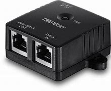
- Depending on the location in the transmission path where the power supply is combined with the data, the PoE Injectors can be divided into 2 groups: PoE switches (endspan) and PoE adapters (midspan).
Depending on the transmitted power and data rates, the 802.3at standard encompasses 2 versions:
type 1 – for devices compliant with 802.3af and with power transmission employing 2 pairs of min. Cat.3 cable, with max output power of 12.95 W
type 2 – with max output power of 30 W, transmitted via min. Cat.5 cable
The standard also defines two types of PoE implementation:
option A – power is sent together with the data on pairs 1/2 and 3/6
option B – power is sent on pairs 4/5 and 7/8 (unused in Fast Ethernet networks, in the case of Gigabit Ethernet the pairs are used both for data and power transmission).
PoE Diagrams
The power supply unit may implement both or just one of the PoE types, while remaining compliant with the standard. So, the powered device must therefore support both modes, however, as it turns out in practice, not all end devices are fully compliant with the standard. This may be the reason for the lack of compatibility with some PoE power supplies.
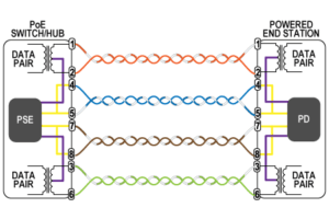
Wiring diagram for a PoE switch (endspan) and an 802.3af (802.3at type 1) powered device.
Option A – violet color, option B – yellow color.
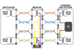
Wiring diagram for a PoE injector (midspan) and an 802.3af (802.3at type 1) powered device.
Option A – violet color, option B – yellow color.
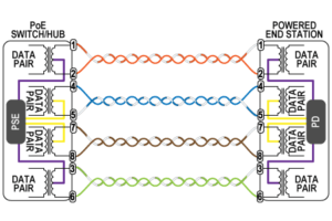
Wiring diagram for a PoE switch (endspan) and an 802.3at type 2 (PoE+) powered device.
Option A – violet color, option B – yellow color.
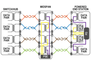
Wiring diagram for a PoE injector (midspan) and an 802.3at type 2 (PoE+) powered device.
Option A – violet color, option B – yellow color.
PoE testing procedures and classes of powered devices
PoE standard has been optimized for safety. In addition to a safe voltage range, the devices must communicate according to established procedures. Before providing the supplying voltage, the PoE Injector tests the connection. The current is limited to mill amperes and is applied to determine the actual type of the PoE implemented in the powered device (with the help of characteristic resistance of about 25 kΩ used for this purpose in the device). In addition, this procedure allows for checking the continuity of the line.
Optional classification of equipment compliant with 802.3af standard provides useful information about its power requirements. It is based on the measurement of the current flowing when testing the connection. The equipment is classified as follows:
| Class | Output power of power sourcing equipment (PSE) | Power consumed by powered device (PD) |
| 0 | W 15,4 | W 0,44 •12,95 |
| 1 | 4,0 | 0,44 • 3,84 |
| 2 | 7,0 | 3,84 • 6,49 |
| 3 | 15,4 | 6,49 • 12,95 |
| 4 | 30 | 12,95 • 25,5 |
Devices compliant with 802.3at also communicate with one another using Layer•2 power management protocol for enhanced power allocation, LLDP•MED (extended version of the protocol for auto•detection of devices). With such communication it is possible to determine the actual power demand with accuracy to 1.11W. The PoE Injector forwards the information on the demand for power at regular time periods.
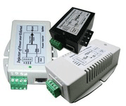
Non-standard solution – passive PoE
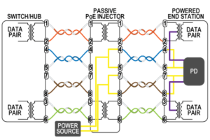
Passive PoE transmits power through selected conductors of UTP/FTP cable. The supplying voltage can be connected directly to the powered device or converted by a special adapter. There is no communication between the power source and the powered device • the power is provided continuously. The wiring is usually made according to option B of IEEE 802.3af (use of free pairs 4/5 (+) and 7/8 (•) in 10/100 Mbps Ethernet networks).
There are power devices that can operate in Gigabit Ethernet networks. They use transformers that enable transmit power along with the data (like in 802.3af option A). It should be noted that passive PoE solutions are not compatible with the 802.3at standard and are not recommended for use in professional networks.
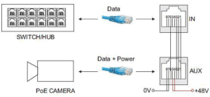
Learn About Vorp Energy Products:
Solar Powered Surveillance Kits

Leave a Reply